A Portrait of the Shropshire Union Canal and its Branches
An eBook by Cyril J Wood
![]()
![]()
In Preparation
Disclaimer
Author cannot be held responsible for any disputes caused by information included within this eBook. While all attempts have been made to verify information provided, the Author does not assume any responsibility for errors, omissions or contrary interpretation of the subject matter herein. Any perceived slights of specific people or organizations are unintentional. Information contained within this eBook is provided solely for the user's information and, while thought to be accurate, is provided strictly "as is" and without warranty of any kind, either expressed or implied. The Author will not be liable to the readers for any damages, direct or indirect, arising out of use of information provided within this eBook. Proceeding beyond this page acknowledges acceptance of this disclaimer.
What is today referred to as the Shropshire Union Canal System is, in effect, a collection of canals built at different times ranging from the old Chester Canal of 1772 to the relatively modern Liverpool and Birmingham Junction Canal opened in 1835. Consequently, each part of the system has its own unique features and character.
To tell the story of how this system of canals came together, we have to start with the earliest… The Chester Canal.
The Chester Canal came about due to a need to transport salt, cheese and other agricultural products to Chester. It was also hoped to link with the Trent and Mersey Canal at Middlewich where the raw materials brought around the coast to Chester (then a thriving port) could be transported to the pottery industry located at Etruria and the surrounding Potteries area in Staffordshire. The canal could also transport the finished products to Chester for loading onto coastal vessels and distribution to other destinations.
The proposal was for a canal to run from a basin connected to the tidal River Dee below the weir at Chester, pass through the city and head across the Cheshire Plain to Middlewich and join with the Trent and Mersey Canal. The canal was promoted as a broad waterway allowing passage of flats and barges from the River Dee without the need for trans-shipment of cargoes.
There were many objections to the proposed route, the main opposition being from Francis Egerton; The Third Duke of Bridgewater, the driving force behind the Bridgewater Canal that also connected with the Trent and Mersey Canal. The Duke’s objection was that the Chester Canal would take trade away from the Northern end of the Trent and Mersey and hence the Bridgewater Canal. Hi objection, under the circumstances, was quite understandable.
Samuel Weston originally surveyed the route of the Chester Canal in 1772 with the Act of Parliament allowing its construction, being obtained the same year. Unfortunately, due to pressure exerted by the Duke of Bridgewater and his supporters, the act did not include a junction with the Trent and Mersey and forbade it from approaching within one hundred yards of the canal.
A hasty revision of the canal’s route had to be made and it was decided to shelve the Middlewich line making Nantwich as its new terminus. This change of route was to have far-reaching implications with regard to the prosperity of the canal, but it was thought that cheese, dairy and other agricultural products transported from the Nantwich area should provide sufficient trade to justify the construction of the canal. Construction commenced with the first sod being cut by Joseph Taylor, the Mayor of Chester, in April 1774.
Initial progress on the construction of the canal was good as the canal utilised part of the original Roman moat surrounding Chester’s city walls. The only major construction works on the route were the triple staircase lock at Northgate in Chester, an aqueduct over the River Gowy at Beeston and the double staircase lock at Bunbury. However, things soon started to slow down due to a combination of factors. With the modification to the original plan preventing a connection with the Trent and Mersey Canal, many of the financial backers withdrew their support.
Samuel Weston was inexperienced in canal building and was soon replaced by a succession of engineers who were also inexperienced. The other engineers were Thomas Morris and Josiah Clowes. They were also dismissed. There was also the added problem of the canal being constructed on unstable running sand at Beeston. The bridge at this location collapsed and the two-step Beeston Staircase Locks were causing problems. This was a problem that would reoccur later on causing the canal to terminate at Beeston for many years. The canal was eventually completed in 1779 but it did not enjoy the financial success that it’s promoters had envisaged.
With the financial problems brought about by the denial of a junction with the Trent and Mersey Canal, the original backers pulling out and the lower levels of traffic on the canal than originally envisaged, the canal soon ran into financial problems. Many landowners were owed money by the Chester Canal Company from the original purchase of land for the canal’s route. They tried, in vain, to recoup the amounts outstanding. But matters came to a head in 1782 when some of the landowners concerned decided to drain Bunbury Reservoir, one of the canal’s main sources of water, in protest to their being owed money. Their actions brought canal traffic past this point to a standstill. They had hoped to hold the Canal Company to ransom until their claims were satisfied and payments due to them made. Unfortunately, the company did not have sufficient funds to pay the landowners and the canal became unusable past this point. Their actions may have sealed the fate of the canal and prevented the generation of any revenue from which they might have received some payment. In other words… they shot themselves in the foot.
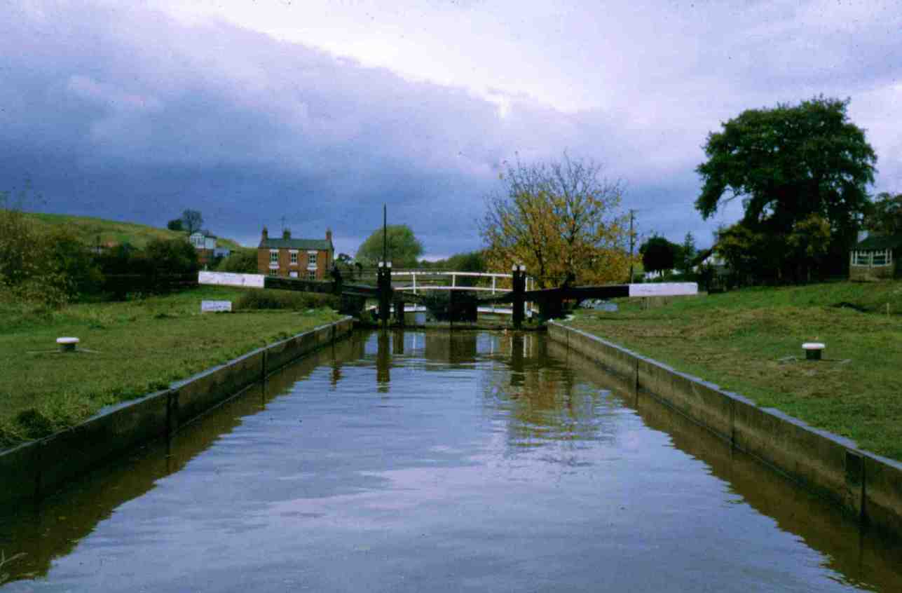
Five years later, in 1787, the lower chamber of the Beeston Staircase Lock collapsed due to the running sand, on which the canal was constructed, undermining the lock’s foundations and causing it to collapse. As the Chester Canal Company was not in a financial position to rectify the problem, the canal terminated at Beeston Wharf just below bridge 107. This was to be the terminus for the foreseeable future until the canal was absorbed into the Ellesmere Canal when Thomas Telford realigned the canal and replaced the staircase lock with two conventional locks, the lower of which possessed a revolutionary cast iron chamber that was not affected by the running sand beneath it. The second chamber was replaced with Beeston Stone Lock which was located a quarter of a mile along the re-routed section of the canal.
The Chester Canal had been semi-derelict since 1782 when disgruntled landowners owed money from the construction of the canal drained the water supply reservoir at Bunbury rendering the canal un-navigable above this point. Consequently, the canal suffered extremely low water levels. Additionally, the Beeston Two Step Staircase Lock, which was built on shifting sands, collapsed as did the main road bridge (107) adjacent to Beeston Wharf for similar reasons, causing the terminus of the canal to be Beeston Wharf for many years. Telford’s solution to the problems surrounding Beeston was to realign the canal from Beeston Wharf towards Tilston, replace the staircase lock with two conventional locks separated by a pound a quarter of a mile in length. The new upper Beeston Stone Lock was conventional in construction but for the lower lock Telford decided to construct a unique replacement.
|
Beeston Iron Lock on the Shropshire Union (formerly Chester) Canal... |
|
note the chamber constructed from flanged cast iron plates |
The replacement was unique in that the chamber was constructed from flanged cast iron plates. This structure would be less prone to collapsing due to the action of the shifting sand beneath it. It is a tribute to the engineering skill of Thomas Telford that the lock has withstood the test of time. It required major remedial work in the 1980’s when one of the foundation tie bars fractured. But normally the lock requires minimal maintenance apart from the usual gate and paddle replacements and the odd coat of paint. The foundation tie-bar problem may be raising its head again as British Waterways currently advise that, even though it is a broad lock, only one boat passes through at a time due to a slight bellying-out of the plates that form the lock chamber walls which could cause two craft situated side by side to get stuck whilst the lock is filling. We shall have to watch this space for future developments.
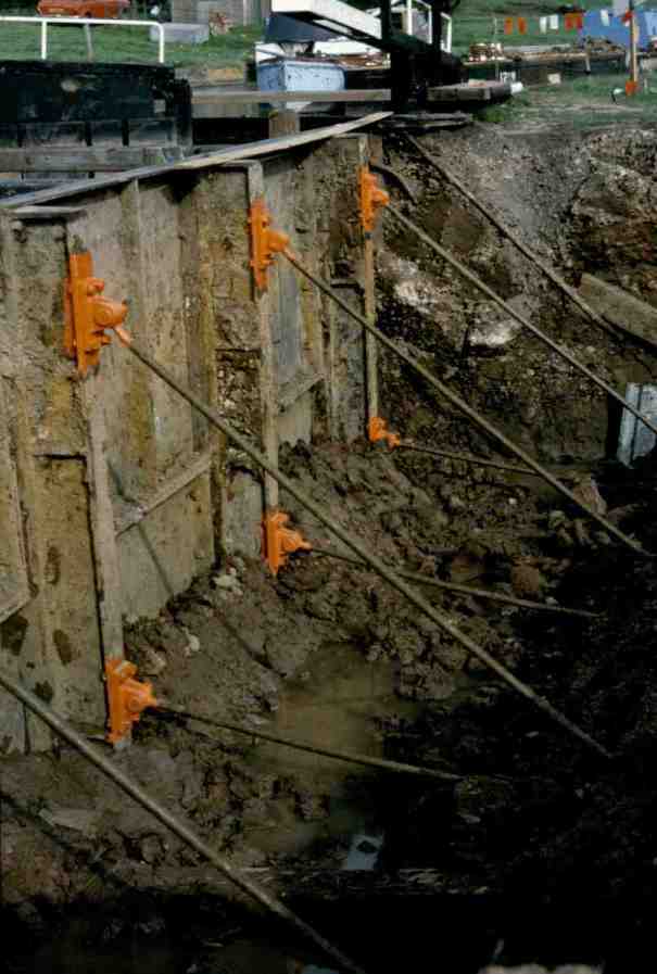
Tie bars connecting the side plates to the foundations of Beeston Iron Lock
At Chester, the canal utilised part of the old Roman moat that was situated on the outside of part of the walls. The canal descended down to the River Dee via Northgate Five Step Staircase Lock. This lock lead to a large semi-tidal dock that was connected to the River Dee. This dock must have been problematic due to the varying water levels as the Dee rose and fell with the tides.
The Wirral Line has its roots firmly planted within that of the Ellesmere Canal. Thomas Telford's vision for the Ellesmere Canal was to join the Rivers Severn, Dee and Mersey by canals. Part of this route was the canal connecting the River Dee at Chester with the River Mersey at Whitby better known by its contemporary name of Ellesmere Port. This name is derived from the fact that the canal from Ellesmere in Shropshire ended here and so Whitby became the Port of Ellesmere or... as we know it today, Ellesmere Port. As previously mentioned, the Chester Canal was lowered to the level of the River Dee by the Northgate Five Step Staircase Lock. Telford converted this lock into the three step staircase lock that we know today. Immediately after the bottom chamber the canal makes a ninety degree turn to the right into Tower Wharf. The canal maintains this level all the way to Ellesmere Port. Parallel with the latter part of Tower Wharf is a dry dock and adjacent to it is the first lock of the River Dee Branch. This lock takes the place of the fourth chamber of Northgate Five Step Staircase Lock and after a ninety degree bend to the right is another lock that took the place of the fifth chamber. The branch is now on the original route of the canal. If one was to stand at the top of Northgate Staircase Lock and look towards the River Dee it will be noticed that the direction of the staircase lock is exactly in line with the bottom lock of the River Dee Branch, so confirming its origins. At the end of what was the semi-tidal dock is an extra lock gives access to the River Dee.
At the Ellesmere Port end of the Wirral Line there are also three locks. There is also a lighthouse that indicated the location of the canal basin entrance at night. Whereas these locks once gave access to the River Mersey, from 1894 when the Manchester Ship Canal was constructed this access was cut off and craft had to use the Manchester Ship Canal as far as Eastham. This also made the lighthouse redundant. There was an access lock at Ellesmere Port which incidentally, was the point that water was let into the completed section of the Ship Canal but this was later removed due to lack of use.
Chapter 3 - The Ellesmere Canal
On 18th June 1791, a meeting took place at Overton on Dee between John Kynaston, William Mostyn Owen and the Reverend John Robert Lloyd to discuss a proposal for a canal to link the rivers Severn, Dee and Mersey. The proposed canal would be used to transport goods and materials to and from the iron works at Brymbo and Bersham, slate from the quarries in the Llangollen area, lead, lime, coal and other minerals from mines scattered about the area and also to connect with the Shropshire industrial area. It would appear that the proposed canal would not suffer from the lack of trade opportunities that the nearby Chester Canal did.
Later that year, John Duncombe, an engineer from Oswestry, was employed to make an initial survey of the route and to attend Parliament to help promote the Ellesmere Canal’s first Act.
In the meantime, further meetings took place and additional interested parties joined the group of promoters. The Ellesmere Canal Company was formed and the public were invited to purchase shares. This was at the height of the “Canal Mania” period and the purchasing of these shares took place at Ellesmere on 10th September 1792. Such was the public’s confidence and enthusiasm for the scheme that, it is reported that close to one million pounds was promised by purchasers of the shares sold at £100 each, but this may be an exaggeration. As a result of the success of the public subscription to the proposed canal, on 17th July 1793 a committee was formed to execute the scheme.
One of the Committee’s first tasks was to appoint William Jessop as Chief Engineer for the canal. At the same time, Thomas Telford was given the appointment of Surveyor. These appointments brought together the duo that was to make a lasting impression, not only to the Ellesmere Canal but also to the canal network as a whole.
Chapter 4 - The Montgomery Canal
Chapter 5 - The Birmingham and Liverpool Junction Canal
(The Canal That Never Was)
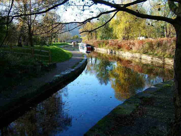
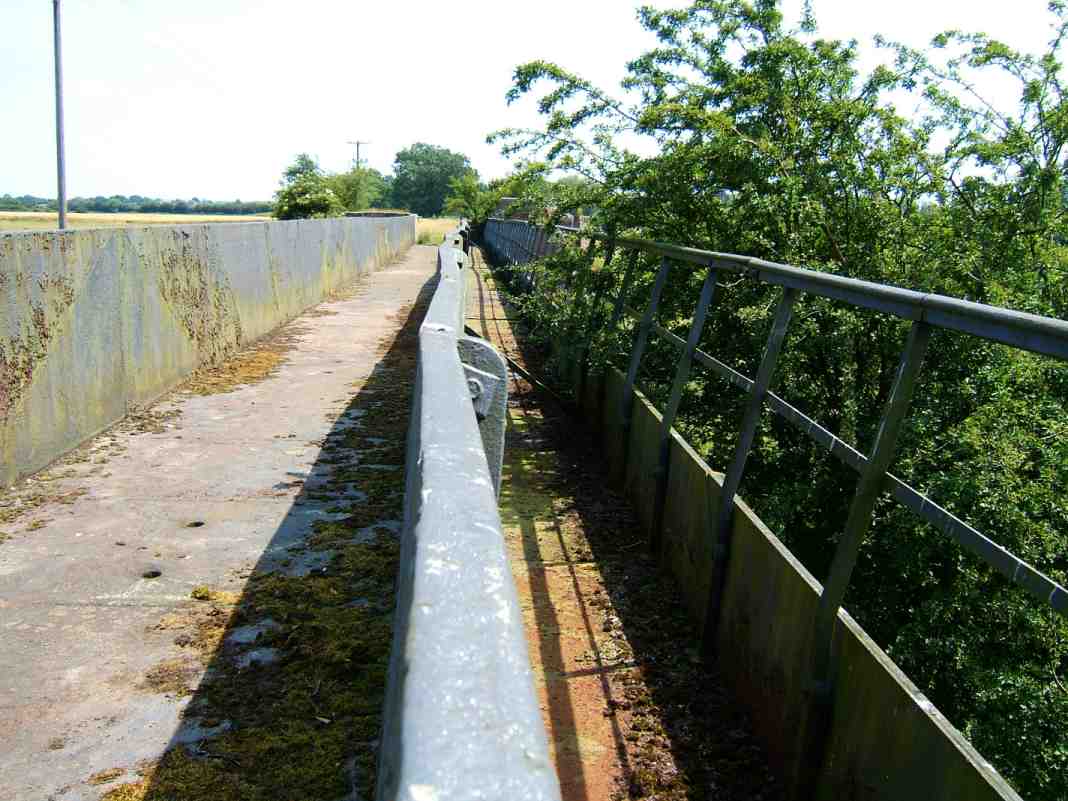
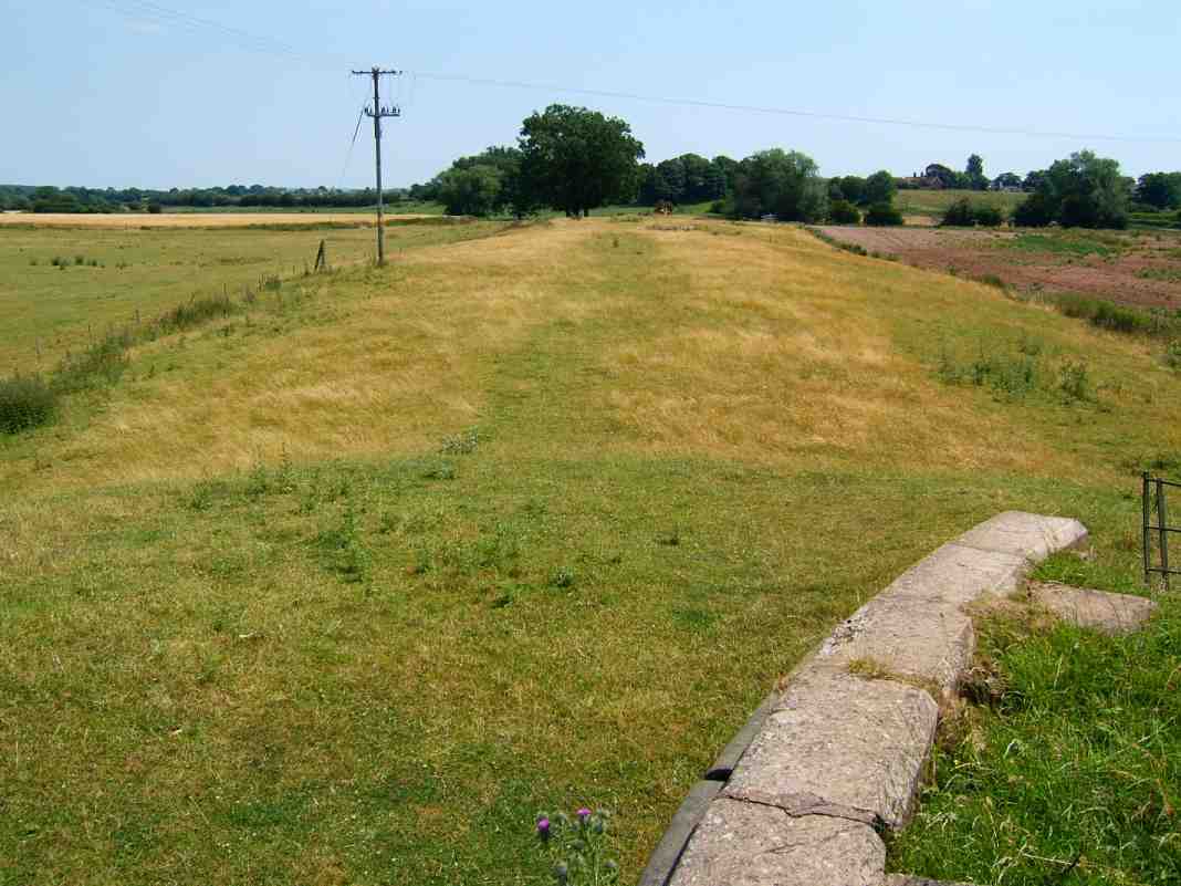
During the history of our canal system there have been many canals that were planned or even construction started then aborted for various reasons. A prime example of this is the Ffrwd (or Frood) Branch of the Chester and Ellesmere Canal which is better known today as the Llangollen Canal.
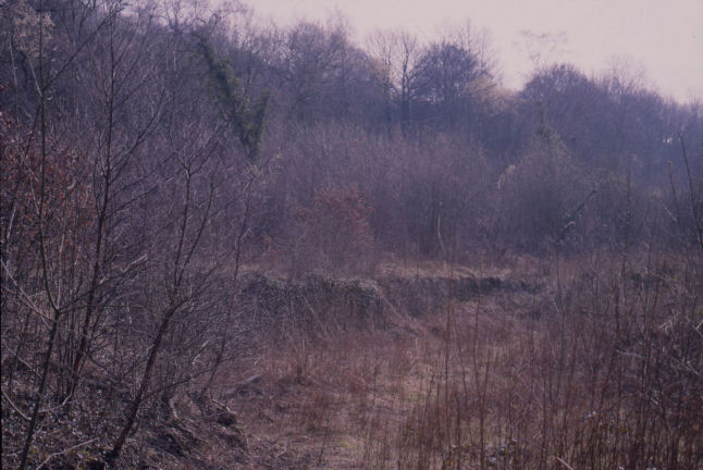
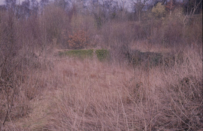
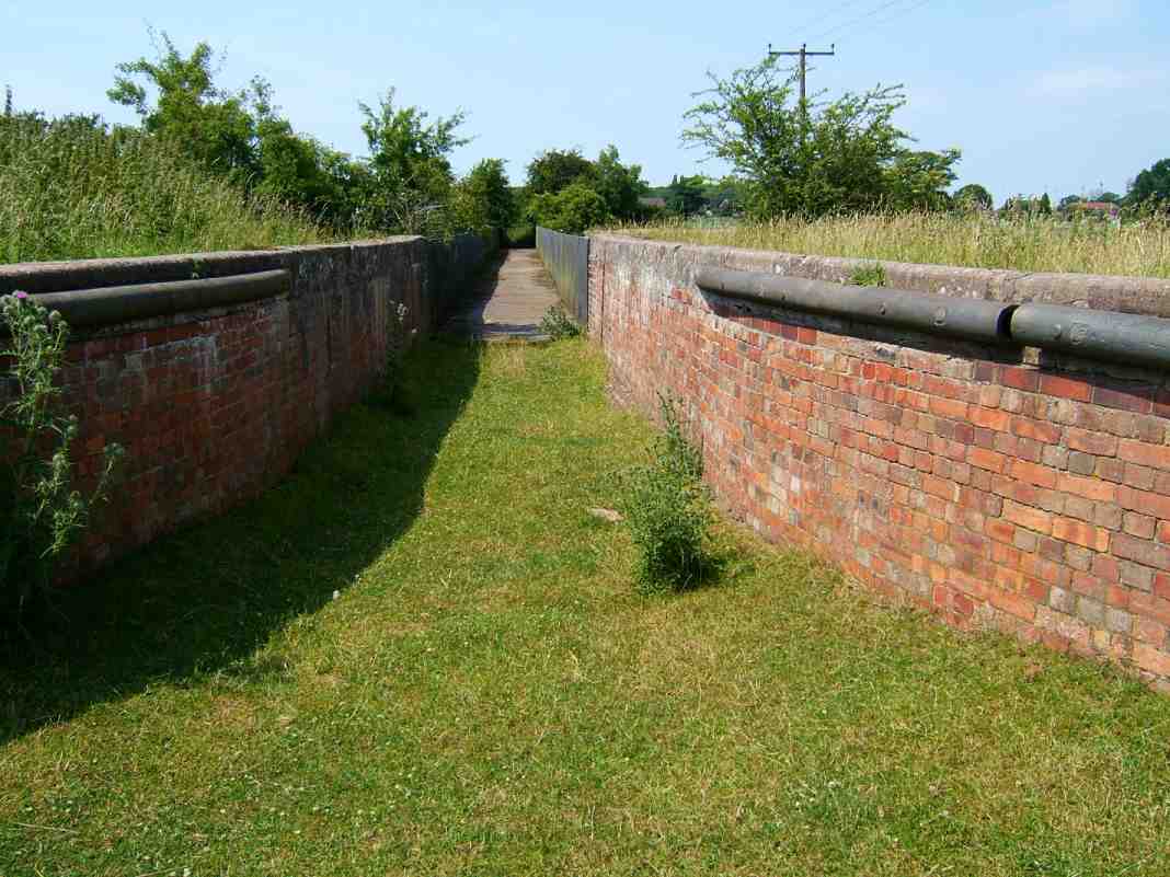
What appears to be a stone wall is actually the canal bank
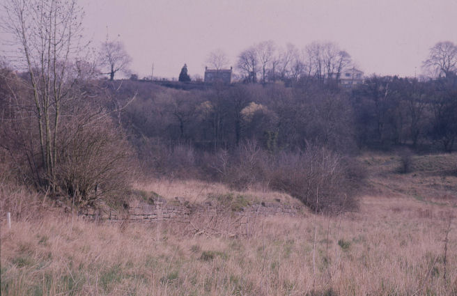
The line of the canal is well illustrated here in an "S" bend running off to the right
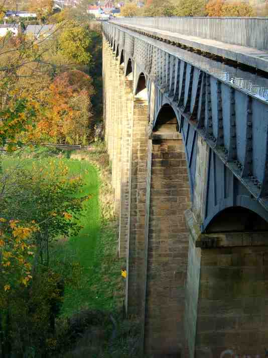
From the outset of the planning stage of the Ellesmere Canal there were two camps of supporters. One camp supported what was known as the Western Route which was to run from the village of Netherpool (now Ellesmere Port) on the banks of the River Mersey, across the base of the Wirral Peninsula to Chester where it would make a junction with the existing Chester Canal at Tower Wharf, the original line of which connected with the tidal River Dee below Chester Weir. It was planned that craft would go down this branch into the tidal River Dee, cross over to the opposite bank of the river before climbing over one hundred metres up the Welsh Hills towards Wrexham, passing through many locks towards Brymbo and a tunnel, 4215 metres long, beneath Ruabon Mountain. It would then make a junction at Trevor with a navigable feeder from the Horseshoe Falls above Llangollen then cross the River Dee Valley on the Pontcysyllte Aqueduct (after the prototype Longdon on Tern Aqueduct was deemed successful… see the chapter dedicated to this understated structure) and a short distance later cross the Ceriog Valley on Chirk Aqueduct. At Welsh Frankton a branch would extend to Ellesmere and Whitchurch whilst the main line would descend to Llanymynech and Welshpool with a branch to Shrewsbury.
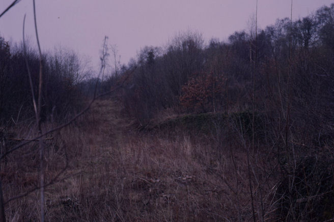
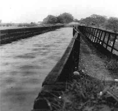
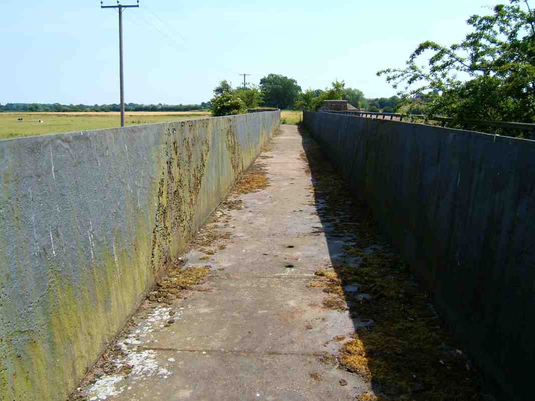
The two photographs above show what appears to be part of a lock chamber
The terrain through which the tunnel would pass can be seen in the distance and notice the "towpath" on the right
The heavy lockage up to Trevor required by this route was, from the outset, a cause for concern and it was proposed to construct a reservoir at the end of the Ffrwd Branch to act as a water source. In 1796 an experimental boat lift was built on the Ffrwd Branch by Edward Rowland and Exuperius Pickering. Rowland and Pickering patented their design for what they called a “lock machine” (basically another term for a boat lift similar to the one constructed at Anderton but on a smaller scale) in 1794 and the Canal Committee allowed them to build a prototype lift at their own expense. As the lift was built on a canal that ultimately, was never to be completed, the committee agreed to pay two hundred of the eight hundred pound cost of building the lift. Had the route been completed and the lift deemed successful, its implementation could have eliminated some of the concerns surrounding the heavy lockage on this route and may have offered a viable alternative to locks, thus minimising the water supply requirements for the canal. Unfortunately, few details (and no remains) of the lift are available and its exact location remains a mystery. However, it is believed to have been situated in the Ruabon area (possibly at the western end of the long tunnel) and used a rack and pinion mechanism to lower and raise caissons in its operation. The lift was dismantled when the Western Route was dropped but there exists a similar design on the German waterways at Dorftmann. Exuperius Pickering’s other claim to fame is the design and construction of the Chain Bridge in 1814 across the River Dee at Llantisilio adjacent to the Horseshoe Falls. It is interesting to note that the Plas Kynaston Canal referred to later was also known as Pickering's Canal named after Exuperius Pickering.
The Eastern Route was identical to the Western Route from Netherpool to Chester. From there onwards it utilised the partially derelict Chester Canal across the Cheshire Plain to Tattenhall where a junction would be made and the canal was to climb above the Cheshire Plain towards Whixall with a branch to Whitchurch. The canal would then make its way to Ellesmere and link up to the Western Route at Welsh Frankton. In this scheme, at the western end of Pontcysyllte, the navigation would end at Trevor Wharf where there were to be transhipment facilities from the mineral railways serving the nearby quarries and mines. There would be a one mile branch canal into the Plas Kynaston Iron Works which is now infilled with the Water Line to Llantisilio being used as a navigable water feeder. The branch canal to Plas Kynaston was actually built and was known as the Plas Kynaston Canal or Pickering's Canal.
|
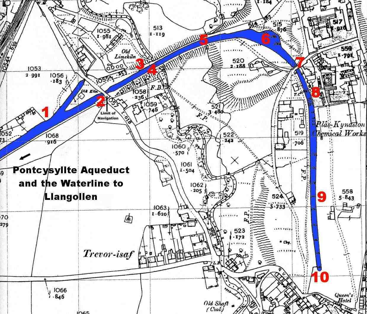
A map dated 1812 which shows the line of the Plas Kynaston or Pickering's Canal. |
|
The numbers in red are points referred to in the text and location of the photographs |
|
(Map - Flexsys Rubber Products) |
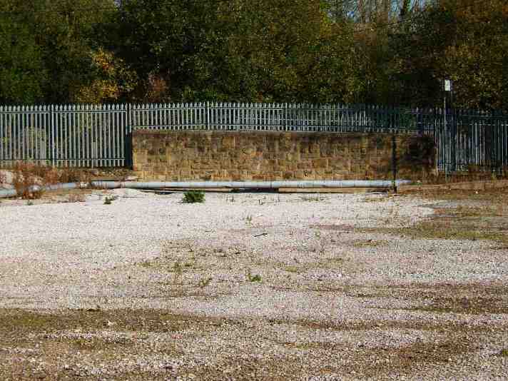
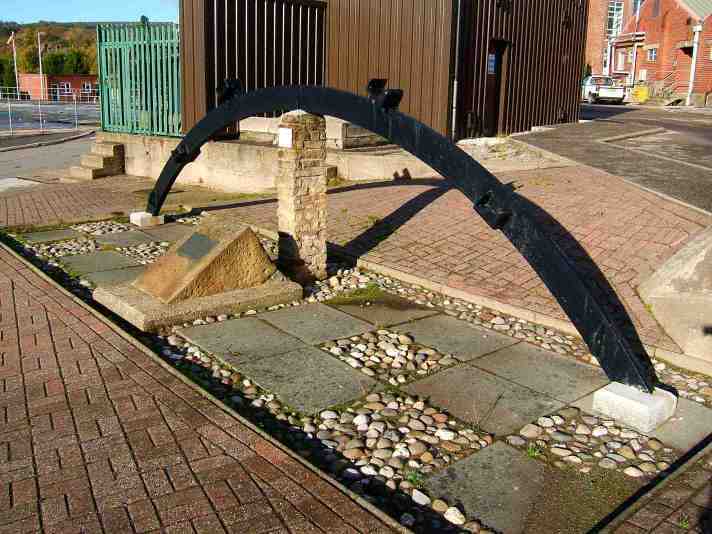
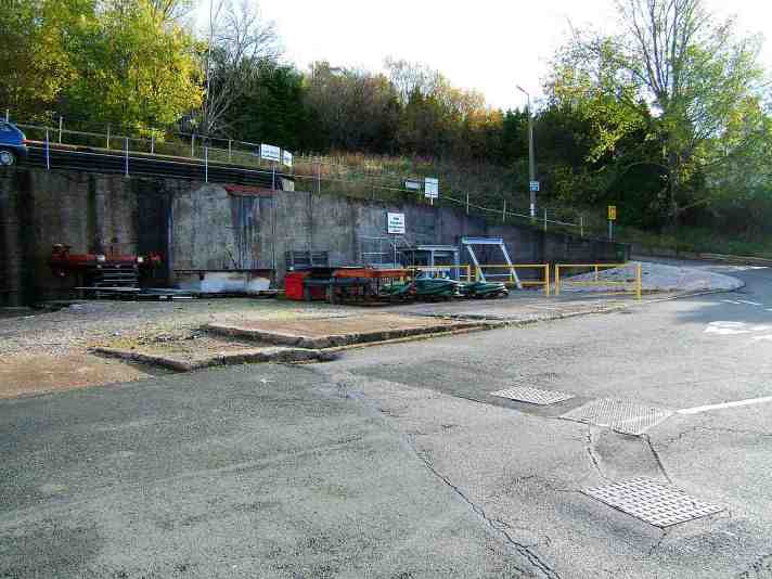
1 - The remains of the Ruabon Arm looking towards Scotch Hall Bridge
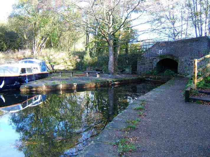
2 - The end of the Ruabon Arm and the start of the infilled section of the Plas Kynaston or Pickering's Canal (beneath the bridge)
The location of the Plas Kynaston Iron Foundry is remembered by a plaque within the Ruabon Works complex which was later the home of Monsanto Chemicals before then Flexsys Rubber Products. Within the complex is a commemorative plaque alongside the display of a preserved cast iron roof truss from one the original buildings. The foundry was built specifically for the fabrication of the cast iron plates used in the construction of Pontcysyllte Aqueduct and the partial (when originally built) cast iron trough of Chirk Aqueduct. After casting the plates were transported to the site of the aqueduct along a branch canal that was to originally form part of the Western Scheme. The canal was in use up to the 1940's and possibly later, although it is now in-filled the line of this branch can be seen and traced with the aid of an old map within the Flexsys Complex (formally the Monsanto Chemical Plant).
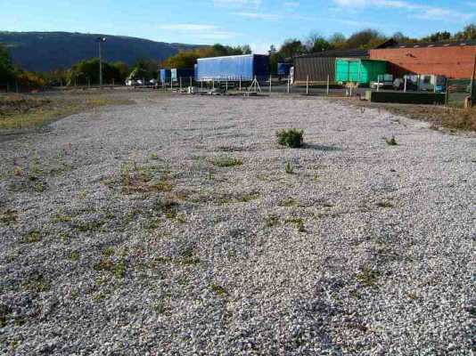
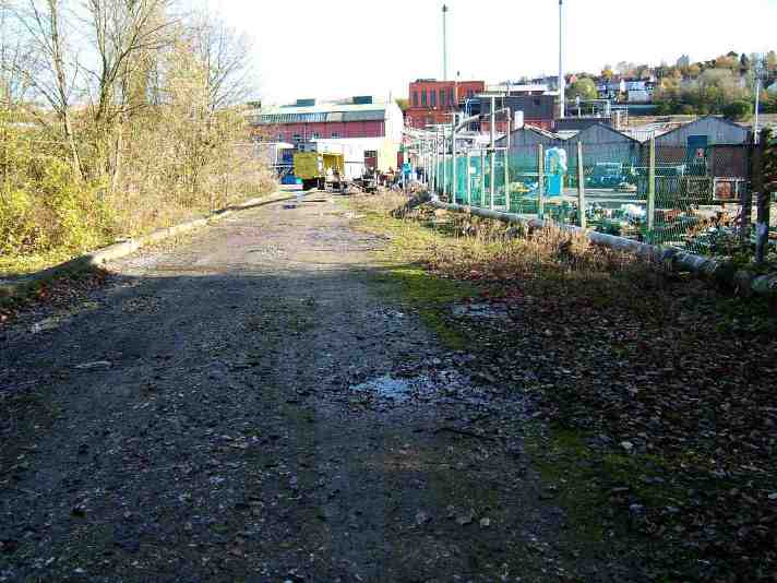
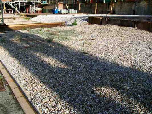
3 - The infilled section is the gravelled area emerging from Flexsys' Lorry Park
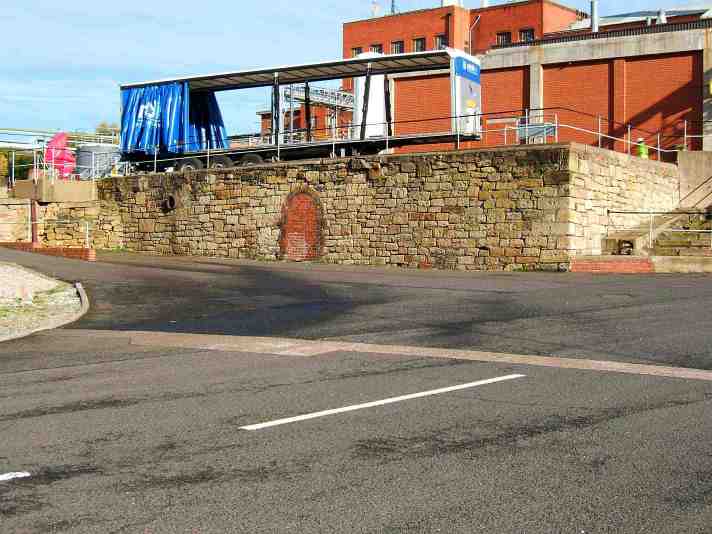
The bridge at the end of the right hand transhipment arm forms the start of the infilled section (1 & 2 on the map). On the other side of the bridge the canal disappears beneath Flexsys’ lorry parking area (3) and its line can be traced in the form of a gravelled area towards the remains of a bridge (4).
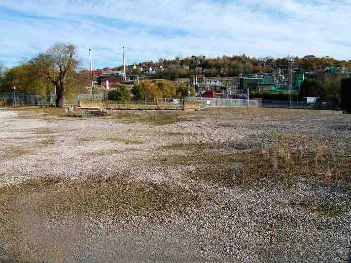
4 - From the lorry park the infilled canal heads towards the remains of a bridge
4 - The remains of a bridge which carried an access road across the canal
This bridge must have been a quite modern structure (possibly 1920/30’s) as it does not appear on earlier O. S. Maps and the stonework looks too regular to have been built earlier. Following on from this bridge, this isolated section of canal was in water quite recently and was a fish hatchery (5).
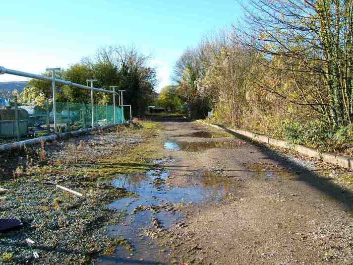
5 - The location of the Fish Hatchery
|
5 - Looking in the opposite direction from the previous photograph, |
|
the in-filled line of the canal runs towards the Flexsys Complex |
A straight section then runs into the main part of the Flexsys Plant where it curves around to the right, past the commemorative plaque and a cast iron roof truss (6)...
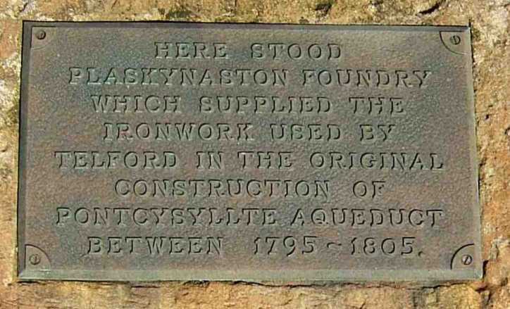
6 - The commemorative plaque
6 - The cast iron roof truss and location of the plaque above
6 - The location of a lime kiln or loading wharf adjacent to the line of the canal
|
7 - Looking from the lime kiln towards the remains of the bridge in the centre of the photograph |
...to the remains of a canal bridge. The remains (7) consist of the side wings and the bricked-up bridge hole. Adjacent to the bridge is an inspection hatch in the ground and, if lifted, water and the remains of the canal bed can be seen.
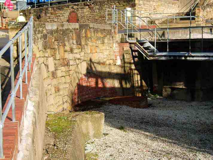
7 - The remains of the bridge with the lime kiln in the background
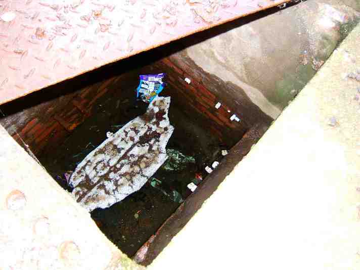
7 - With the inspection hatch adjacent to the bridge lifted, canal water can be seen below
During the Second World War, the site was owned by Monsanto Chemicals and some of the plant’s output was moved by canal. Photographs exist in Wrexham Library that document boats being loaded on the canal at this time.
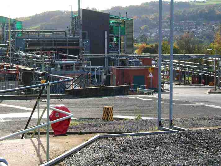
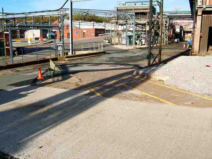
A story that was related to me recently by a Flexsys employee tells of a large mobile crane coming into the works to provide heavy lifting facilities to remove some metal storage tanks. The crane was parked to make the lift and one of the site’s longest serving employees came and informed the engineers that the crane could not be parked there as it was on top of the old canal bed (8) and it might collapse under the weight. Needless to say, the crane was hastily moved to a more stable location before the lifting took place. The tanks that were removed sat on steel girders placed over the line of the canal to prevent the tanks foundations subsiding. From here the canal ran in a straight line (9) and finished close to the boundary fence at the Ruabon Village end of the plant (10).
8 - The remains of the bridge are behind the plant in the centre of the photograph
8 - The location of where the removed storage tanks used to be
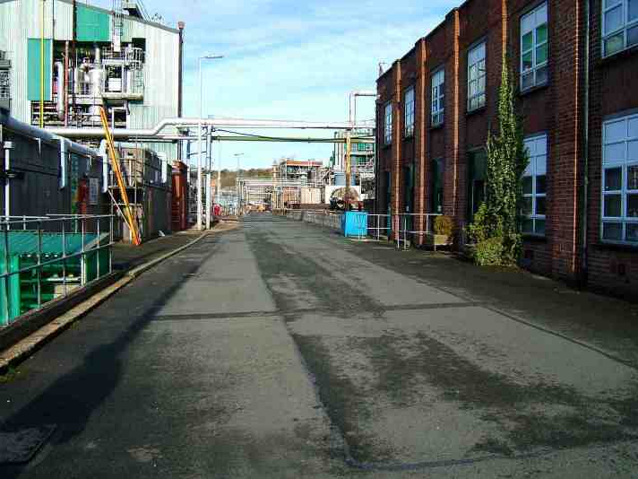
9 - The building on the right is built over the location of the canal
|
10 - The end of the canal is marked by the yellow steel barriers to the centre/right of the photograph |
In 2008 the Flexsys plant closed and under terms of an agreement the land it occupied had to be returned to public usage. There is a chance that after the plant has been dismantled the canal is reinstated and marina moorings located at the far end of the canal. Whether this plan comes to fruition remains to be seen.
The route that the Ellesmere Canal was to ultimately take was the Western Route and in 1793 an Act of Parliament was passed to enable the construction of the canal. Due to the immense scale of construction on the two giant aqueducts at Pontcysyllte and Chirk, an early start was made on their construction whilst work on the canal proper began with the Wirral Line from Netherpool and parts of the route in the vicinity of Wrexham and Trevor for the transportation of building materials required for the canal’s construction. The work on the Wirral Line included construction of a new branch to the River Dee from Tower Wharf and converting the original Northgate five step staircase lock into the current three step staircase lock with the removed chambers being replaced by the two new locks on the River Dee Branch. Had the original five step staircase lock been left in its original form it would have challenged Bingley Five Rise on the Leeds and Liverpool Canal as one of the Seven Wonders of the Waterways.
It was soon evident that the line of the canal including the two aqueducts was going to be more expensive to construct than at first thought. So expensive in fact that a complete rethink of the line of the canal was made. Another consideration was that of water supply. Even though Thomas Telford had raised the level of Lake Bala (Llyn Tegid) by six inches, constructed an exit weir at the northern end of the lake where the River Dee flows out of the lake and the Horseshoe Falls… also on the Dee above Llangollen to provide the head of water for the canal, there would still be problems supplying water to the locks down to Chester and the line from Welsh Frankton to Shrewsbury.
It was because of these problems that the Eastern Route was looked at again. The route that was eventually settled upon was a modification of the Eastern Route but instead of having a junction at Tattenhall, the Chester Canal would be utilised as far as Hurleston near Nantwich where the canal would climb up to Whitchurch, (which it would reach via a branch canal above Grindley Brook) cross Whixall Moss to Ellesmere (with a branch to Prees), use the planned junction at Welsh Frankton for the Shrewsbury and Llanymynech branches but with the canal terminating at Ruabon except for the junction with the Water Line. Parliament was approached and the necessary Acts passed in 1796.
It is evident that the canal’s construction was fraught with political, financial and engineering problems. One interesting fact concerning the Pontcysyllte Aqueduct is that the aqueduct and part of the line of the canal approaching it was under threat of being converted into a railway viaduct. One source even tells that there were suggestions to convert it into a viaduct even before it was completed. But, common sense has prevailed and I for one am glad that this monument to Thomas Telford has remained an aqueduct.
When the Ellesmere Canal was opened in it’s entirety in 1813, the Ffrwd Branch, completed in 1805, was completely isolated. The branch left the proposed main line from the basin at Gwersyllt and ascended a flight of locks, through Ffrwd and Oak Alwyn until it reached a reservoir intended to help supply the canal’s summit level with water. There are conflicting reports as to whether or not this three mile length of canal was ever filled with water but, I would hazard a guess that it was as local mine owners complained of damage caused to their mines by the presence of water leaking from the canal and the canal company spent £9000 on remedial work.
After the abandonment of the Western Route, part of the canal bed was used by a railway line although isolated stretches of what is obviously a canal route can still be located. I remember seeing it in the late 1960’s when at least one bridge was still intact and some of the original canalside furniture could be seen. Parts of the canal bank were lined with local stone, mooring bollards were in evidence and the canal bed, overgrown as it was, looked as though it was still capable of holding water. Needless to say I didn’t have a camera with me at that time (a mistake I try not to repeat these days)! In later years, when I was locating the route and taking photographs of the remains of the canal, I was told by local residents that after heavy rainfall water stayed in what was left of the canal bed for days before eventually evaporating or draining away, implying that the canal bed and its puddled clay lining is still watertight. I think that it is safe to say that this stretch of canal will not be a candidate for the Waterways Recovery Group’s work sheets
The Ffrwd Branch is not unique in being isolated from the main line of the canal it was supposed to be joined to but it remains a good example of “jumping the gun” as far as construction is concerned. Today, the visible remains shown earlier are part of a park in Ffrwd near Brymbo. The Flexsys Rubber Complex closed in 2010 and the manufacturing complex has now been dismantled. There are now plans to redevelop the area and the plans include reinstatement of the canal to a new marina at the end of it.
Chapter 7 - The Newport Branch
Chapter 8 - The Shrewsbury Canal and Longdon on Tern
When driving through the village of Longdon on Tern there appears to be nothing remarkable about it until the River Tern is crossed. A glance across the fields will reveal something black and unusual lurking in the distance. On closer inspection it is the Longdon on Tern Aqueduct which carried the Shrewsbury Canal across the River Tern and the adjacent flood plane. The cast iron plates that make-up the trough are reminiscent of the mighty Pontcysyllte Aqueduct. This is not surprising as Longdon on Tern was a "practice run" for Pontcysyllte where Thomas Telford's theories of cast iron construction were put into practice... albeit on a smaller scale.
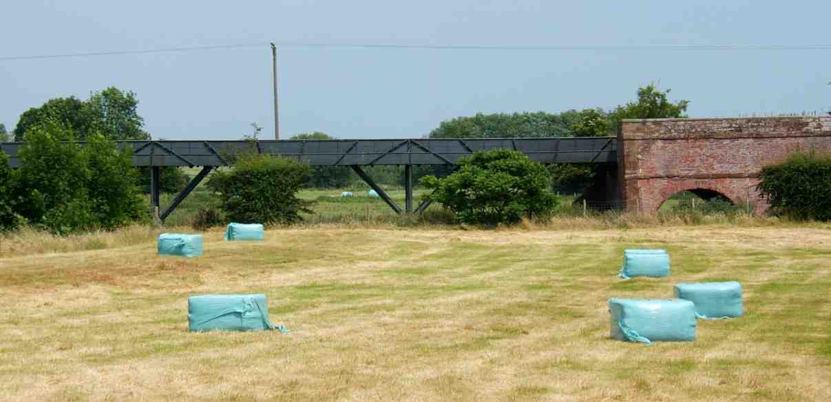
The first glimpse of the Longdon on Tern Aqueduct across the fields
Longdon on Tern Aqueduct is the oldest surviving cast iron aqueduct in the world. But it wasn’t the first. That honour goes to a much smaller cast iron structure… the forty four foot (fifteen metres) long Holmes Aqueduct located on the Derby Canal, designed and constructed by Benjamin Outram with, no doubt, some help from William Jessop who was also involved in the Derby Canal. The Holmes Aqueduct opened a few weeks before Longdon on Tern and so pippped it to the post for being the first cast iron aqueduct in the World. The location of Holmes Aqueduct was in the centre of the City of Derby where it carried the canal across a stream but unfortunately it no longer survives as it was demolished as recently as 1971 during road reconstruction and realignment works. This leaves the Longdon on Tern Aqueduct as being the oldest surviving cast iron aqueduct in the World and is a Grade One listed structure and a Scheduled Ancient Monument.
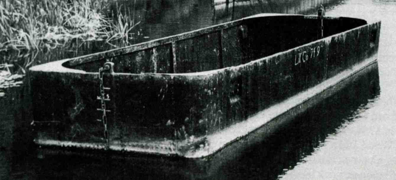
A typical Tub Boat as used on the Shrewsbury Canal
(Photograph - British Waterways)
The Shrewsbury Canal was unusual insomuch that the maximum beam of boats that it could accommodate was 6' 7" (2 metres). It was not designed for narrowboats but for tub boats. These tub boats were horse drawn in trains of of up to twelve but as the locks (some of which possessed unusual guillotine gates) were 81 feet long but were originally constructed with intermediate gates half way along the lock chamber. In later years these gates were removed but even then the locks could only take four tub boats at a time. After 1832, when the canal was connected to the standard width Newport Branch of the Birmingham and Liverpool Junction (now the Shropshire Union Canal from Norbury Junction) specially constructed 6' 7" (2 metre) beam narrowboats were built for use on the canal. Trans-shipment into these boats was deemed impractical and Henry Williams, a long serving employee of the Shrewsbury Canal Company reported to the Committee that it would be beneficial to widen the locks on the canal. It was decided to widen the stretch of canal from Wappenshall Junction to Shrewsbury which was completed in 1834 but widening on the southern Branch to Trench never took place due to width restrictions on the Trench Inclined Plane.
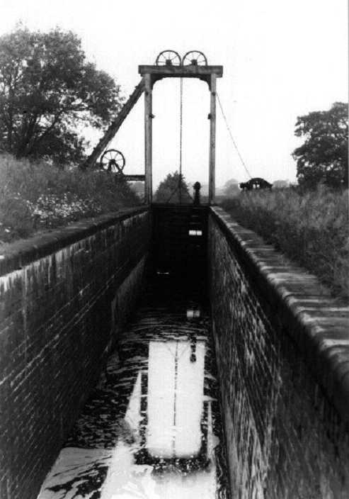
A Shrewsbury Canal lock showing the guillotine style gates
(Photograph - British Waterways)
Another unusual feature of the canal was the lift bridges that would not look out of place on the Llangollen Canal today. Maybe they are another example of Thomas Telford's influences on the canal but there is always the possibility that he first saw these bridges on the Shrewsbury Canal and used the same design on the Llangollen Canal.
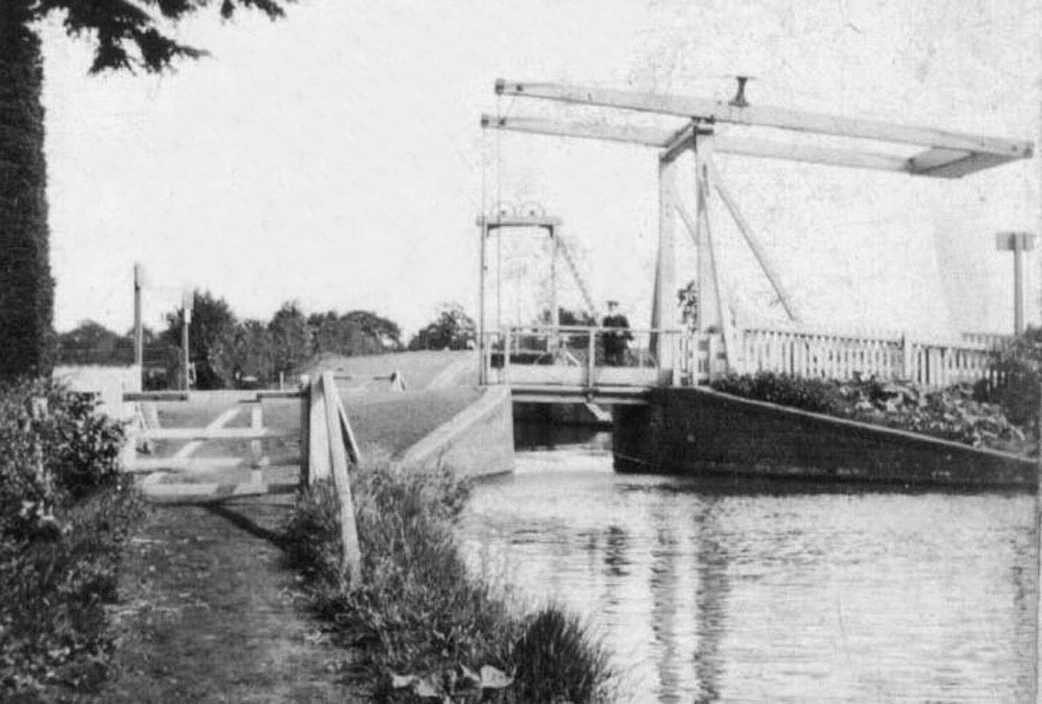
The canal featured lift bridge similar to those on the Llangollen Canal
(Photograph - British Waterways)
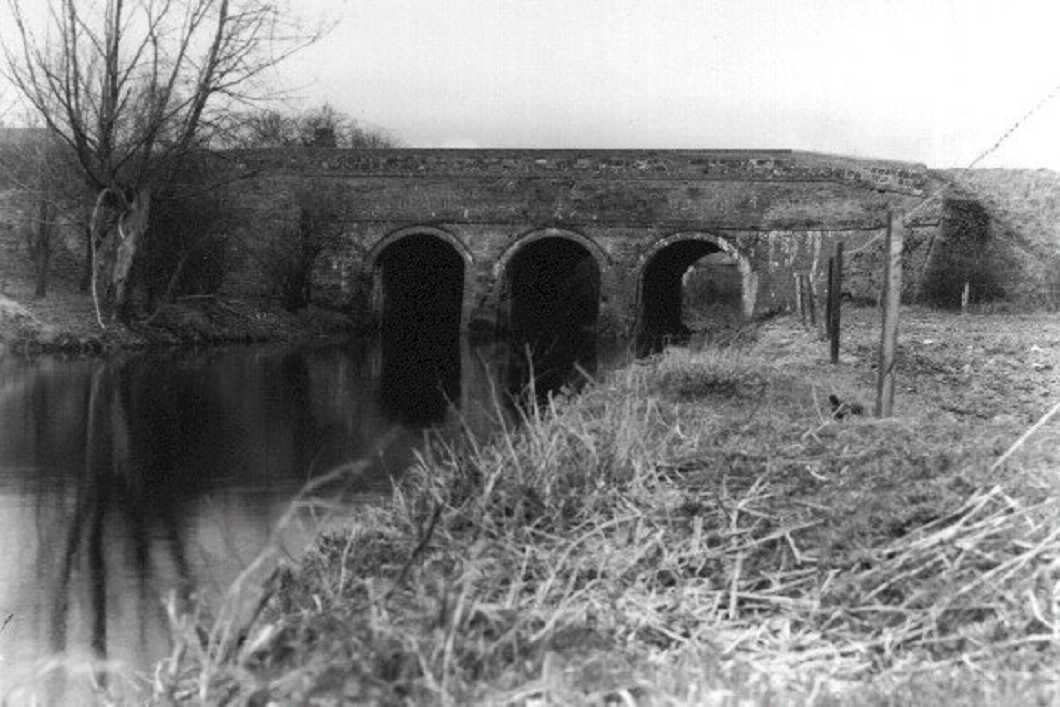
The cast iron aqueduct at Longdon on Tern could, in fact, have been quite different from how it is today. Josiah Clowes was engineer for the Shrewsbury Canal and just like most other canal aqueducts built up until that time he designed, and began to build, a substantial masonry structure sufficient to carry its own weight, that of the water and a thick lining of puddled clay to retain the water not unlike Brindley’s original Barton Aqueduct which carried the Bridgewater Canal over the Mersey and Irwell Navigation. Between 10th and 12th February 1795 the works were washed away by an abnormal flood but unfortunately Clowes’ death prevented him from rebuilding the aqueduct.
|
Rodington Aqueduct was similar to Clowes' original aqueduct at Longdon on Tern but on a smaller scale and with fewer arches |
|
(Photograph - Canal & River Trust) |
|
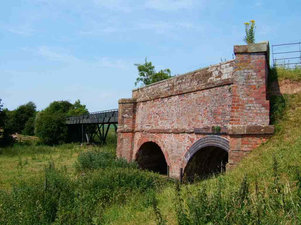
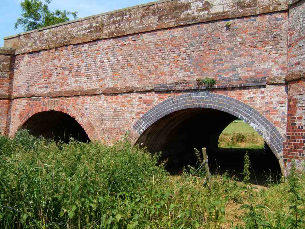
Longdon on Tern Aqueduct... The brickwork abutments on the right and at the opposite end (shrouded in foliage) are from Josiah Clowes' earlier structure |
|
A closer view of the brick abutments from Clowes' original aqueduct, some of which collapsed during a flood |
The replacement for Josiah Clowes was Thomas Telford. He was appointed on 28th February 1795 to take over construction of the canal and just fourteen days later the company approved the erection of a cast iron aqueduct at Longdon by William Reynolds & Co., the cost of which was not to exceed £2000. It was stated that the plan was to be approved by Telford and, although often attributed to him, it seems unlikely that the idea was actually his. In fact Telford later wrote that the idea was that of Thomas Eyton, chairman of the Shrewsbury Canal Company and the design determined by both Reynolds and Telford.
|
Longdon on Tern Aqueduct seen from above... |
|
... note the similarities to the Edstone Aqueduct (shown later) on the much later Stratford |
|
Canal, especially the towpath being at the same level as the water trough bed |
The same location when the aqueduct was in water in the 1940s
(Photograph - Canal & River Trust)
The dry water trough is in near perfect condition
The flanging on the cast iron plates is reminiscent of Pontcysyllte's...
... as can be seen in this photograph of Pontcysyllte Aqueduct
The brickwork abutments "lead-in" to the cast iron trough.
The resulting aqueduct was designed and built in very a short period of time. The iron plates were cast at Ketley in Shropshire and the aqueduct’s new cast iron section built between the surviving masonry ends of Clowes original aqueduct by March 1796. This cast iron section was 186 feet long and 16 feet high and consisted of two troughs side by side… one containing the navigable watercourse and the second containing the towpath, the floor of which was at the same level as the canal bed. Beneath the troughs, cruciform-section struts radiate in different directions to support the structure.
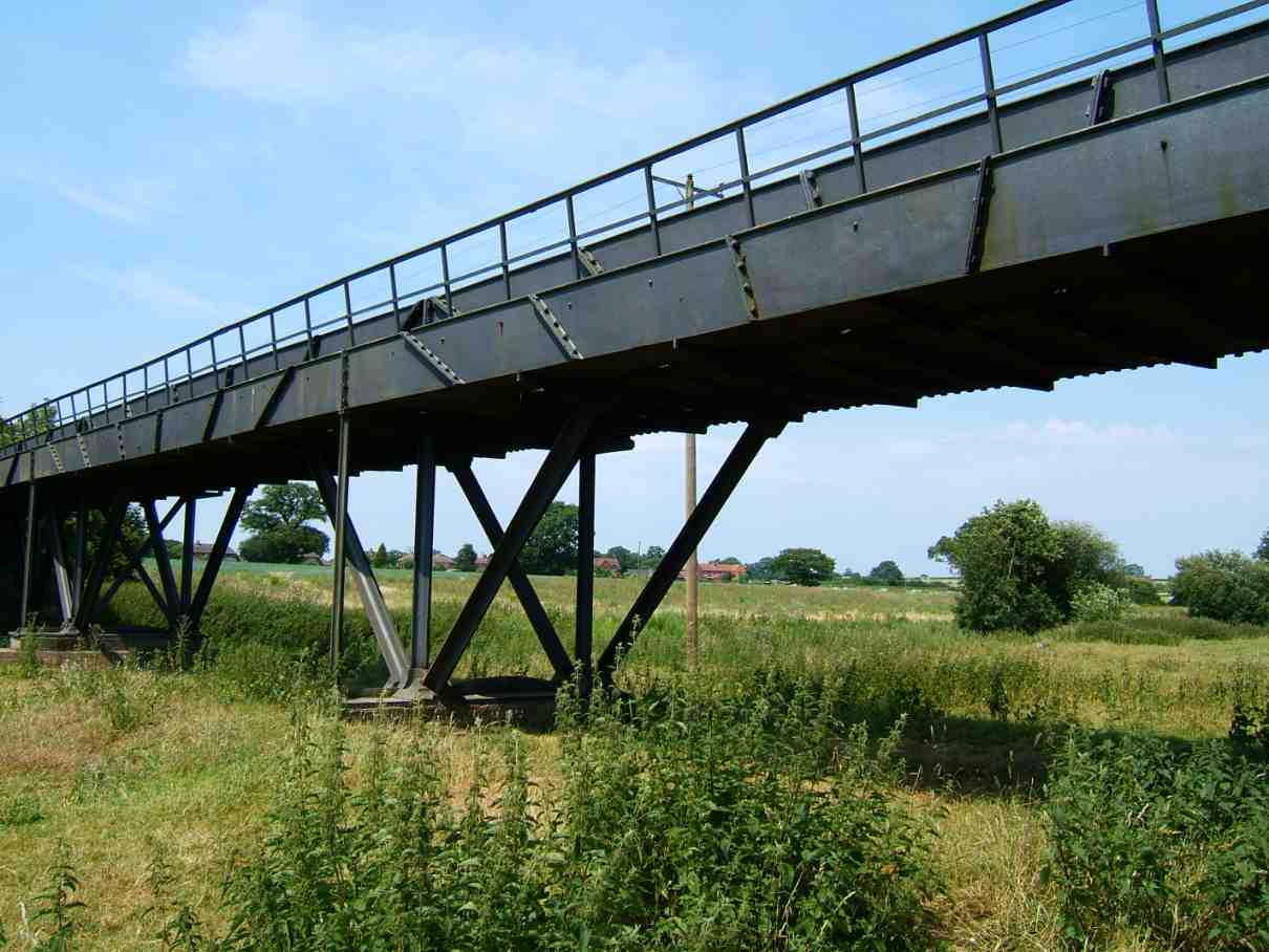
Longdon on Tern Aqueduct seen from below...
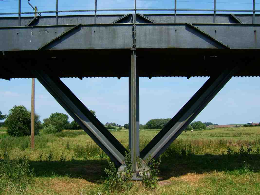
... note the cast iron supporting struts instead of masonry pillars
|
Today the Shrewsbury Canal that crossed the aqueduct is no more and all that remains of it at Longdon on Tern is a mound in a field |
At the end of August 1794, almost three years before the completion of the Shrewsbury canal, Emanuel Galiere was appointed “to superintend the fire-engine at the Trench Inclined Plane”. Amongst the earliest items to pass down the plane would be the cast iron plates to be used on the Longdon on Tern aqueduct further along the canal.
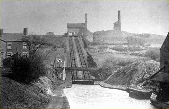
The Trench Inclined Plane
(Photograph - Canal & River Trust)
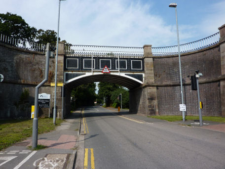
Following the success of the Longdon on Tern aqueduct, Telford went on to construct not only the Pontcysyllte and Chirk Aqueducts (the latter having a cast iron trough embedded into the masonry) but other cast iron aqueducts such as the nearby Duke’s Drive or Kynnersley Aqueduct on the Newport Branch of the Birmingham and Liverpool Junction Canal (later known as the Shropshire Union Canal) built around 1797, the slightly larger and identical Dog Lane Aqueduct at Congleton on the Macclesfield Canal, Nantwich Aqueduct and Stretton Aqueduct on the main line of the “Shroppie”. These three examples carry the canal across main roads and not surprisingly, all used identical castings and are of similar dimensions… seven metres (20feet) wide by seven metres (20 feet) high with a span of ten metres (30 feet) . The brick abutments are virtually identical except for the ornamental cappings at Stretton that are reminiscent of the Pontcysyllte Aqueduct’s piers. No doubt this was to recognise the fact that Telford's canal - The Birmingham and Liverpool Junction (or Shropshire Union Canal) was crossing Telford's A5 trunk road, or at least his rebuild of the earlier Roman Road called Watling Street that originally formed the route of the A5.
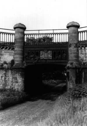
Duke's Drive (or Kynnersley) Aqueduct also on the Shrewsbury Canal, sadly now demolished
(Photograph - Canal & River Trust)
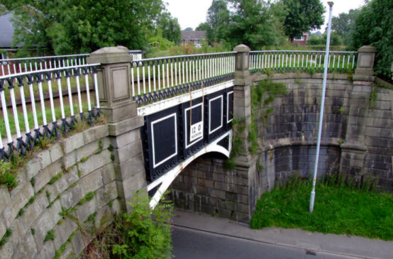
Dog Lane Aqueduct - Congleton - Macclesfield Canal
Nantwich Aqueduct - Nantwich - Shropshire Union Canal
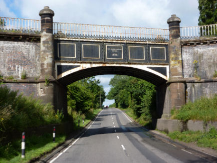
Stretton Aqueduct - Stretton near Brewood - Shropshire Union Canal
Even though the importance of the Longdon on Tern Aqueduct is synonymous with the design of Pontcysyllte, the effect on the design of the 700 foot long, 70 foot high Chirk Aqueduct also warrants comment. Telford was aware of the effect that puddled clay had on aqueduct design and decided to lighten the weigh at Chirk by constructing partially hollow arches and providing the masonry trough with a waterproof cast iron lining. It was not however constructed with a completely cast iron trough... only the bottom of the trough was made from cast iron. There may have been many reasons for this but the two most likely ones are as follows... 1. Chirk was required to be completed before Pontcysyllte due to the the trade already using the lower reaches of the canal, hence, the trough was only partially cast iron with plans to make it fully cast iron in the future. 2. Telford was not totally convinced as to the suitability of the material as the aqueduct at Longdon on Tern had not yet proved itself. Whatever the reasons, after completion in 1801 leakage proved to be a problem but it was not until 1869 that Chirk received a trough that was one hundred percent cast iron. The underside of the trough can be inspected with the canal in water as there are access holes situated in each of the hollow arches specifically for this function.
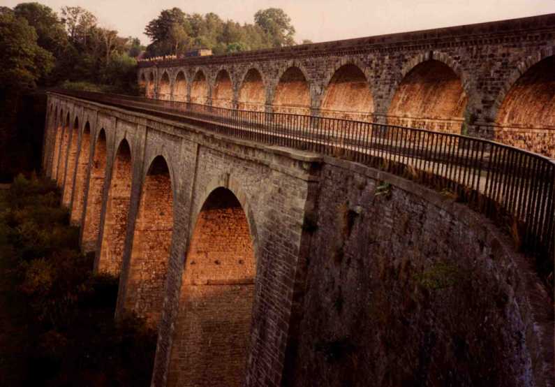
Chirk Aqueduct overshadowed by the much later railway viaduct
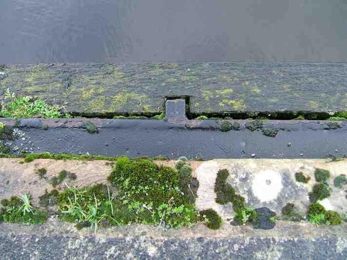
A close-up of the top of the cast iron trough that lines Chirk Aqueduct
Although the aqueduct at Longdon on Tern is still in existence it no longer holds water and the canal either side of it has been in-filled. A similar structure (albeit a larger example) can be found on the southern section of the Stratford on Avon Canal in the shape of the Edstone (or Bearley as it is also known) Aqueduct. The trough used on this aqueduct is longer than Longdon at 146 metres and is supported by masonry piers rather than cast iron support struts and higher with the trough being 12 metres at its highest point. It was built in 1814 by William Whitmore (coincidentally the successor to Josiah Clowes and Samuel Porter) and carries the canal across a road, a railway line, a small river and meadows and is the longest cast iron aqueduct in England.
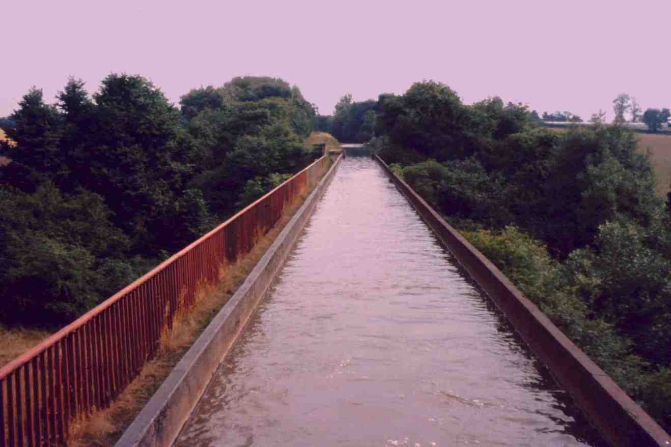
The Edstone (or Brierley) Aqueduct on the Stratford Canal... the largest cast iron aqueduct in England
The story surrounding the Longdon on Tern Aqueduct is an interesting one and the importance of this modest and, in some ways "Heath Robinson" structure cannot be understated. Without it the mighty Pontcysyllte and beautifully proportioned Chirk Aqueducts, plus the numerous other cast iron aqueducts would, most probably, not have been built in the way that they were.
Chapter 9 - The Middlewich Branch
Chapter 10 - Railway Ownership and Amalgamation
Chapter 11 - Decline, Leisure and the Future
| 1772 | - | Chester Canal proposed and surveyed by Samuel Weston |
| April 1774 | - | Construction of the Chester Canal commenced |
| 1779 | - | Chester Canal opened |
| 1782 | - | Bunbury Reservoir drained and the canal closed at Bunbury |
| 1787 | - | Lower chamber of Beeston Staircase Lock collapsed |
| 18th June 1791 | - | Meeting at Overton to discuss proposed Ellesmere Canal |
| 10th September 1792 | - | Shares in Ellesmere Canal sold |
| 17th July 1793 | - | Committee formed to execute the Ellesmere Canal scheme |
| 1793 | - | William Jessop appointed chief engineer for the scheme |
| 1793 | - | Thomas Telford appointed surveyor for the scheme |
or select another book below...
|
|
|
"Canalscape" and
"Diarama" names and logo are copyright |
Up-dated 16-03-2014